
Abstract
With the introduction of Fibre Channel, the disk storage enclosure is no longer Just a Bunch of Disks. Consequently, it can be difficult for the IT professional to deal with the challenges and complex issues that a Fibre Channel disk storage enclosure can create.
In the past, a JBOD would provide the basics: power, cooling and protection. It may have even provided some LED fault indicators that would display the state of the enclosure elements. Some of the individual elements of the enclosure might have even been replaceable while letting the enclosure continue to operate.
Unfortunately, a simple JBOD becomes difficult to manage in a Fibre Channel environment. Enterprise System implementations with Fibre Channel can include such items as a very large number of disks and enclosures, lights-out data centers and remote locations. Using a simple JBOD in these types of environments will result in lost information and undesirable events.
With Fibre Channel, the disk storage enclosure has become an essential component of the total solution. The disk storage enclosure must be capable of offering massive storage capacity, advanced data protection and availability, and increased reliability and serviceability. The disk storage enclosure now becomes the foundation of a long-term mass storage strategy.
In order to meet these requirements, the enclosure must be intelligent enough to recognize failures on its own, isolate and analyze those failures, and communicate with various host systems. The enclosure elements must be redundant and support hot-swap. It is essential that industry-standard rack designs are supported and that the enclosure density be as high as possible.
In addition, Fibre Channel creates a new level of complexity for an enclosure. Management of the Fibre Channel loop within the enclosure is important to maintaining the integrity of the whole loop. Providing loop management can relieve each host of the burden of dealing with loop failures within the enclosure while providing easy configuration and support.
In The Beginning
Ever since the introduction of 5 ¼ Winchester disks an enclosure has been necessary. These first disk enclosures were simple, providing only the basics: power, cooling and a case to protect the disks. These enclosures would commonly hold more than one disk and for that reason were called a JBOD, or Just a Bunch of Disks.
When one of these simple disk enclosures failed, it was difficult to determine what happened. Was it the fan, the power supply or one of the disks? The JBOD designers added some LED indicators to display power and fan faults and this was fine for a desk-side enclosure. However, in a data center things were different. Most data center managers didn't have the resources to wander around looking for lit fault indicators. In this instance, most everyone relied on the host system to recognize the failure and generally, a fault within a simple JBOD made it inaccessible. Unfortunately, this usually resulted in system downtime until the fault was repaired.
Simple enclosures are also very difficult to manage. If something inside failed, typically it was not customer replaceable. Enclosure case designs were such that a well stocked tool kit was required and often the entire box would have to be removed from the rack. Calls to field support meant prolonged downtime and expensive replacements.
Some improvements were eventually made to disk enclosures to address management and supportability. The designers created field removable components and in certain cases provided the ability to hot plug some of these components. Recent enclosure features have also included redundant components to provide protection from single-point failures. These redundant components would take over operation if a component in the redundant group failed. This would allow the data center manager some additional time to replace the failed component. Of course, if no one recognized that something failed, that additional time was of no value. This frequently would be disastrous, particularly if the other components in the redundant group failed before the original failure was corrected. A data center manager would now be faced with multiple replacements and even more downtime.
Simple JBOD and Fibre Channel
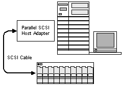
With Parallel SCSI, configurations are simple. Because of cable distances of at most 12 meters, host systems and disks are never far from each other. A Parallel SCSI configuration can have only 15 devices per host adapter and many configurations contain an average of only 8 disks. Since nearly all available multiple disk enclosures can contain at least eight disks, the entire configuration is usually comprised of a single JBOD. Multiple Parallel SCSI adapters, though, can mean multiple disk enclosures. There are also products available such as LUN expanders and SCSI MUXs that can increase the number of devices on a host adapter. Nevertheless, the possible configurations are still not that complex.

Figure 1 Parallel SCSI Configuration
Fibre Channel brings a new level of complexity and flexibility to mass storage configurations. Fibre Channel presents a technological advancement and allows new configurations that are not possible with Parallel SCSI. Using FC-AL (Fibre Channel Arbitrated Loop) a very simple configuration can be created that would be very similar to a basic Parallel SCSI configuration. However, with FC-AL the number of possible disks on a single host adapter rises to 126 and cable distances have increased to 500m and greater. With a disk enclosure that can contain up to 10 disks, a single FC-AL configuration could involve 12 enclosures along a 500m cable.
Unlike Parallel SCSI disk devices that provide a single SCSI connection, FC-AL disks provide two independent connections or ports. This allows for greater performance and improved reliability. This also creates additional complexity. A host system with two FC-AL adapters can now connect to a dual-port enclosure. This can provide some redundancy, as if a host adapter fails or a cable becomes disconnected the host can still access the disks via the other FC-AL adapter.
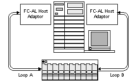
Figure 2 Simple Dual-Port FC-AL Configuration
Using hubs and switches more complex Fibre Channel configurations can be created. This creates a fabric through which many host and mass storage systems can communicate. Unlike Parallel SCSI where everything is within close proximity to each other, complex Fibre Channel configurations can be spread around an entire campus.
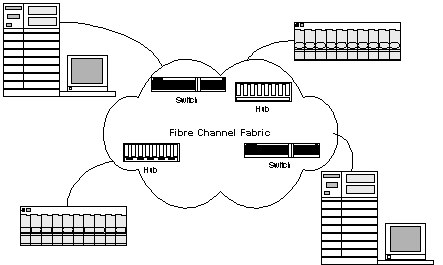
Figure 3 Fibre Channel Fabric Configuration
In a complex environment, such as depicted in Figure 3, a simple JBOD can be nearly impossible to administer. No longer does the storage have to be close to the host. With a configuration that is dispersed about a single building, multiple buildings or even an entire site, how can a data center manager collect the information they need to control their mass storage systems?
Evolution
In order to take advantage of the new technology that Fibre Channel delivers, the JBOD needs to evolve. Fibre Channel increases the number of possible storage devices per host adapter to 126 and interconnect speeds rise to 100MB/s per loop. Cable distances have extended to 500m and greater. Cables themselves can be copper or optical based. FC-AL also provides two independent connections, or loops, which provides a significant advantage over Parallel SCSI. When a host is connected to a dual port device, if a failure on one loop occurs the host can still access the attached devices over the other loop. When both loops are used simultaneously, a combined performance of 200 MB/s can be achieved.
Because of the large number of addressable storage devices on a single Fibre Channel loop, a JBOD must now provide an architecture that is modular and scalable. Incremental growth from 1 to 10 to 1000 disks in a configuration must be easily produced. Construction of Fibre Channel disk enclosure configurations must be flexible, easy to manage, and cost effective.
A variety of hosts and mass storage sub-systems can be attached to the Fibre Channel fabric. The architecture of Fibre Channel allows the user to create a mix of diverse products and operating systems. The interoperability of the JBOD with all Fibre Channel components is required to simplify the creation of these mixed mass storage environments. In addition, by implementing a standards-based Fibre Channel enclosure, configurations will be able to use a common set of services that will improve the opportunities for extended interoperability.
Fibre Channel disk enclosures must also adhere to Open Systems standards in order to be portable. Designing portability into an enclosure protects a user's investment and allows easy movement across mixed mass storage environments. Portable disk enclosures will allow sites to upgrade their environment as technological improvements occur, with minimal impact on operations.
The dual loop feature of FC-AL provides an increase in availability by providing redundant data paths to the disks. Designers must now carry this concept throughout the entire enclosure. The architecture must provide an appropriate level of redundancy so that no single point of failure results in the enclosure becoming completely inoperable or inaccessible.
Reliability must be an essential element in the design of the enclosure. Due to the long cable distances that are possible, physical access to components may be difficult. The components are no longer within a short distance of each other, as would be the case with Parallel SCSI. With the possibility of having a system and mass storage spread out across an entire campus, reliability is a necessity. Since components do fail, redundancy can mask failures giving an appearance of greater reliability, provided the failed components are replaced in a timely manner.
Serviceability is crucial in a Fibre Channel enclosure. The architecture must provide the user with an easy path for maintenance and configuration. All field and customer replaceable components need to be easily exchangeable and hot swappable. Since failures will occur, the disk enclosure must provide the capability to remotely monitor the components and the enclosure environment, and communicate with a host system to report problems and failures.
How Can All This Done?
It is clear that a simple JBOD no longer meets the requirements of the Fibre Channel environment and that the disk storage enclosure has become an essential component of the total Fibre Channel solution. The question is then, what should a disk enclosure look like to meet the requirements of a Fibre Channel mass storage configuration.
Redundant Components and High Availability
To meet the requirements of reliability and availability, the enclosure architecture must be prepared to deal with component failures. In general, the design of a reliable disk enclosure can select one of two different approaches. The first approach is fault prevention, which deals with implementing techniques that avoid the introduction of faults. The second approach is fault-tolerance. Because components do fail, and often there is nothing that can be done to prevent failures, the best approach is to architect fault-tolerance into the enclosure. This is best implemented by identifying all active components within the enclosure and producing groups of redundant components for each. Then, when a component in a redundant group fails, one or more of the remaining operational components would take over. These groups must contain at least two components to be effective and often contain N+1 components. The result is that the failure is masked, or shielded, and unobservable during normal operation by the remaining operational components.
Several methods are available for creating redundant groups and managing failures. For power supplies within an enclosure, load sharing is desirable. In this case N+1 power supplies in the group are functioning simultaneously and all are capable of individually providing the power needs of the enclosure. As a group, the power supplies balance the load between the operational supplies. If one power supply fails, the remaining operational supplies balance the increased load. Cooling fans can be implemented to operate in the same manner by increasing airflow from the remaining operational fans when a fan fails.
A redundant method that works well for temperature and voltage sensors is to duplicate N+1 sensors throughout the enclosure. In a case where four sensors are available, the user accesses a composite of all available sensors. If a sensor fails, the remaining three are sufficient to determine the overall temperature of the enclosure.
A third method involves standby components. The dual port feature of Fibre Channel disks can be used to implement this method. The host performs its normal operations through one port and, when experiencing a connection failure, will switch to the second port and continue. Commonly, software within the host system will perform this switch independent of the host applications.
All active components inside a Fibre Channel disk enclosure also need to be field and customer replaceable, easily exchangeable and hot swappable. To meet the definition of hot swappable, the end-user needs to have the ability to replace components without affecting the operation of the overall system. This includes not only the enclosure itself, but also includes all other attached mass storage and host systems.
Redundancy of active components within the enclosure serves to mask failures such that normal operation can continue. Furthermore, this masking provides additional time to replace the failed component. In a Fibre Channel environment where availability is very important, suspending operations to replace a component is unacceptable. The enclosure architecture must provide the user with an easy path for maintenance and service without interrupting the operation of the enclosure controllers, the disks inside the enclosure, other devices attached to the Fibre Channel connection, and the host systems.
Built-in Hub
A hub is necessary in some Fibre Channel configurations because of the inherent architecture of Fibre Channel Arbitrated Loop, or FC-AL. Each node, or device, on FC-AL acts as a repeater for all other nodes in the loop. In other words, whatever a device acquires from its receiver must be passed on through its transmitter, providing the information was not for the receiving device. The problem occurs when one node goes down, as the entire loop goes down with it. Signal integrity can also be an issue if cable difficulties occur between devices or if a device is unable to provide a proper transmit signal.

Figure 4 Broken Single Loop FC-AL
The hub provides intelligent port detection to tell if a device exists on the loop and bypass circuitry to automatically bypass downed nodes from the loop. The hub is able to isolate and protect the rest of the devices on the loop from an individual node failure. Continued operation among the remaining nodes on the loop is unaffected when the hub removes a device. Maintaining Fibre Channel signal integrity is very important. The hub provides active signal and timing regeneration at each port. This allows the hub to preserve signal integrity over the cables between all connecting nodes.
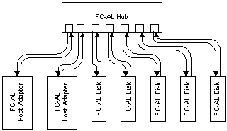
Figure 5 Single Loop FC-AL Using a Hub
To meet the requirements of scalability the enclosure architecture must provide a flexible, easy to manage and cost effective product. To illustrate, consider the following example of a high availability Fibre Channel disk storage configuration. This configuration includes a host system, two FC-AL adapters, two Fibre Channel hubs and as many disk enclosures as required. Hub designs typically include the ability to mix optical and copper interconnects to improve costs and ease configurations. In the illustration, the Fibre Channel connection from the host to the hub could be optical to provide distance and the connection between the hub and enclosures could be copper to reduce costs.
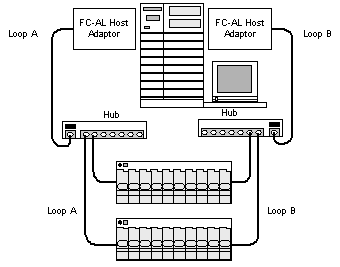
Figure 6 Configuration for Fibre Channel Enclosure without a Built-in Hub
Note: FC-AL cabling will be shown as a single line from now on
While there is nothing technically incorrect with this configuration, the scalability is rather limited. The hub in the illustration will support only five additional enclosures. If the configuration grew beyond a total of seven enclosures additional hubs would need to be purchased. This could be resolved by purchasing hubs with a greater number of connections at the onset, but this would increase the initial cost of the system. The initial cost of the system could be reduced by purchasing hubs with smaller capacity, but this inhibits future expansion.
A significant problem also occurs with hubs in this type of configuration. The hub is able to isolate and protect the rest of the nodes on the loop from an individual node failure. Yet, if a single disk (which is a node on the loop) fails the hub will isolate the entire enclosure. Because of the configuration, the hub is not able to distinguish with any granularity as to which specific device failed, only that a device along a particular loop failed. The hub has no knowledge as to which enclosure contains the failed disk. Consequently, all that the hub can do is isolate the loop that is attached to the enclosure that contains the failed device. This results in potentially operational disks being removed from the Fibre Channel loop.
The need for hubs and the associated problems can be eliminated by including simple hub functionality within the enclosure itself. This built-in hub would provide a primary and expansion port that allowed the chaining together of enclosures in a manner similar to Parallel SCSI. In addition, these ports would allow the mixing of optical and copper connects, as would a standalone hub.
With a built-in hub, the scalability is not restricted. Additional enclosures can be easily attached without any additional hubs or cost. Configurations would be created by attaching the primary port of the first enclosure to the host adapter and attaching the expansion port of the first to the primary port of the second. Additional enclosure can be attached in the same fashion. By also including in the embedded hub design the ability to mix optical and copper interconnects, it is still possible to improve costs and ease configurations.
Flexibility and scalability are greatly improved by integrating the hub into the disk enclosure. The overall cost of the configuration is reduced, as standalone hubs are no longer necessary. Consider the following example (Figure 7) of a high availability Fibre Channel disk storage configuration with the hub functionality built into the enclosure.
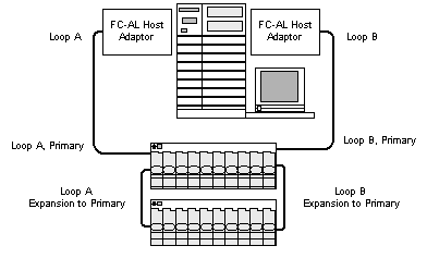
Figure 7 Configuration for Fibre Channel Enclosure with a Built-in Hub
In the illustrated example, the Fibre Channel connection from the host to the first enclosure's primary connect could be optical to provide distance. The connection between the first enclosure's expansion port and the next enclosure's primary connect could be copper to reduce the cost.
The granularity problem that occurs with standalone hubs does not appear with a built-in hub. The embedded hub is able to detect and isolate each individual disk and the enclosure services controller. If a device failure occurs, the built-in hub can remove that device from the loop and not disturb any other devices within the enclosure or attached elsewhere on the loop.
Intelligent Enclosure Services Controller
Components within a disk storage enclosure will fail. If no one recognizes the failure, the amount of time afforded through redundancy to replace the component is of no value. The serviceability and availability of an enclosure can be greatly improved by providing an intelligent controller within the enclosure. This controller would monitor the components and the enclosure environment, and would then communicate with a host system to report problems or failures. This intelligent controller is called an Enclosure Services Device.
The Fibre Channel standard defines a method for transmitting commands and data over a serial line. The command set used with Fibre Channel is SCSI. ANSI has published a standard that defines a set of SCSI commands for an intelligent controller contained within the disk enclosure. This SCSI command set is defined to manage various non-SCSI elements, such as hub circuitry, sensors and power supplies, that are contained within the enclosure. This Enclosure Services Device attaches to the Fibre Channel interconnect in the same manner as a disk or an array.
This is key, as communication to the Enclosure Services Device is accomplished via the same operating system driver as the other Fibre Channel devices. Adherence to this standard furnishes a common interface through existing functionality that in turn reduces the overall cost and complexity. Adherence to this standard also provides an increase in the supportability of the disk enclosure within Fibre Channel mass storage configurations. Implementing SCSI Enclosure Services is important in providing a portable Fibre Channel disk enclosure that will afford easy of movement of the enclosure across mixed mass storage environments.
On the host system, in order to take advantage of the Enclosure Services Device, a background application would provide the monitoring capabilities. This application, upon start-up, would scan for all available Enclosure Services Devices and fetch each enclosure's status. If a problem or failure were discovered, the host system would notify the appropriate personnel via a pager, email, voice mail, etc. On a periodic basis, the monitoring application would repeat the process. The data center manager now has the ability to quickly recognize failures and respond promptly before additional failures occur.
To further reduce complexity and cost, the enclosure services controller would also contain and manage the enclosure's hub functionality. Combining the hub and Enclosure Services Device onto a single controller allows the sharing of common resources such as processors and control circuitry.
Foundation
Because of this necessary evolution, the disk enclosure has become a fundamental element of the entire Fibre Channel solution. The enclosure is capable of a wide range of configurations, from a simple arrangement similar to Parallel SCSI, to being part of a large heterogeneous Fibre Channel fabric. For end-users who wish to have much greater reliability and flexibility than what single disks can provide, Fibre Channel disk enclosures can be used as backend storage for an array controller. This provides tremendous value to data center managers who wish to upgrade to array storage by allowing them to retain their investment in Fibre Channel disk storage enclosures.
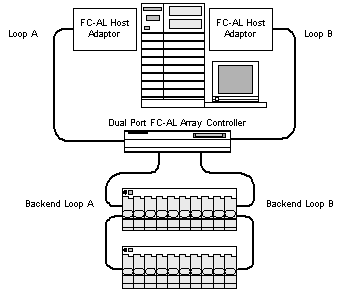
Figure 8 Example Fibre Channel Array with Fibre Channel Enclosures
Disk Enclosure Architecture
The architecture of a Fibre Channel disk enclosure has a collection of requirements that must be met in order to effectively operate in any Fibre Channel environment. The following block diagram illustrates the basic components of a FC-AL disk enclosure.
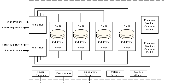
Figure 9 Fibre Channel Disk Enclosure Block Diagram
The enclosure contains two simple hubs, one for each Fibre Channel loop. Each hub connects to the appropriate port on every disk in the enclosure, along with a connection to one enclosure services controller. To allow easy connection to host systems and to provide easy expansion, the hub furnishes two external FC-AL ports.
Each enclosure services controller has an internal connection to temperature and voltage sensors, alarms, and power and fan modules. Through this internal connection, each enclosure services controller can collect status from or provide control of individual enclosure components. In addition, each controller has control over its associated hub. This allows each enclosure services controller to provide a variety of loop management functionality. Depending on the configuration, host systems can communicate with either of the enclosure services controllers via the Fibre Channel loops.
Summary
Fibre Channel brings a new level of complexity to disk enclosures. Because of the technological advancements that Fibre Channel provides over Parallel SCSI, the disk enclosure should be in a position be able take advantage of as many of these advancements as possible. The JBOD that provided only the basics of power, cooling and a case is not going to be able to meet the challenges presented by Fibre Channel.
New configurations that are not possible with Parallel SCSI introduce themselves with Fibre Channel. Complex environments using hub and switches may be employed to create a fabric through which hosts and mass storage subsystems communicate. With increases in the numbers of devices on a loop, cable distance and cable types a disk enclosure needs be flexible and provide support for all possible FC-AL configurations.
The enclosure design should include fault-tolerance and redundant components to provide the reliability and scalability required in complex FC-AL environments. All active components need be redundant and field replaceable to provide the required serviceability. Providing hot-swap is important for all customer and field replaceable components.
Providing a simple hub built into the enclosure can assist in eliminating or reducing the need for external, standalone hubs. This provides unrestricted scalability, improved costs and straightforward configurations. A built-in hub also provides the ability to better manage failed disks without having to remove an entire enclosure from a loop.
The enclosure services controllers should implement the SCSI-3 Enclosure Services specification. This affords a standard disk enclosure that is portable across a variety of Fibre Channel environments.
With the introduction of Fibre Channel, the disk storage enclosure is no longer Just a Bunch of Disks. A properly architected Fibre Channel disk enclosure can help to overcome the challenges that Fibre Channel can create. By taking advantage of the technology advancements introduced by Fibre Channel, the disk storage enclosure can now become the foundation of a long-term mass storage strategy for any business.
Features Checklist for a Fibre Channel Disk Storage Enclosure
|
□ |
Capable of supporting 3 ½ disks in either low-profile or half-height form factors at any capacity |
|
□ |
Capable of providing power and cooling requirements for 7200 RPM, 10K RPM and future disks |
|
□ |
All active components are redundant, including power supplies, fans, controllers, temperature and voltage sensors, and audio alarms |
|
□ |
Customer and field replaceable power supplies, fans, disks, controllers |
|
□ |
All customer and field replaceable components are hot-swappable |
|
□ |
Replaceable GBIC connectors that allow optical or copper connections |
|
□ |
Built-in hub functionality to allow easy expansion and flexibility |
|
□ |
Embedded SCSI-3 Enclosure Services Devices for environmental monitoring and control |
|
□ |
Visual status indicators on all replaceable components and an enclosure level audio alarm |
|
□ |
Efficient rack mounting with highest density possible |
|
□ |
Wide host server and operating system support |
References